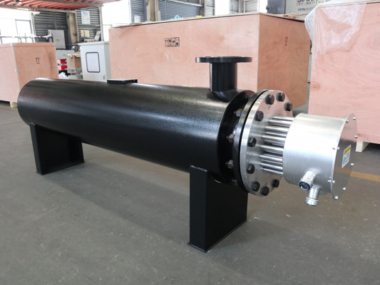
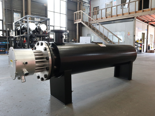
The electric heating nitrogen pipeline heater system is a device that converts electrical energy into thermal energy to heat the nitrogen flowing in the pipeline. Its system structure design needs to take into account heating efficiency, safety, and automation control. The following are its core components and detailed explanations:
1、 Heating main module
1. Electric heating element
• Core heating components:
Fin type electric heating tube: made of stainless steel (such as 304/316L) or high-temperature alloy material, with surface pressed fins to increase heat dissipation area and improve heat exchange efficiency. The interior is made of resistance wire (nickel chromium alloy), filled with magnesium oxide powder (MgO) as an insulating and heat-conducting material, ensuring electrical insulation and high temperature resistance (temperature resistance can reach 500 ℃ or above).
Installation method:
The heating tubes are evenly distributed along the axial direction of the pipeline and fixed to the inner wall or outer sleeve of the pipeline through flanges or welding, ensuring sufficient contact with the heating surface when nitrogen flows.
Multiple sets of heating tubes can be combined in parallel/series, and power regulation can be achieved through grouped control (such as three-stage heating: low, medium, and high power).
2. Pipeline body
Main pipeline:
Material: Stainless steel 304/316L (resistant to dry nitrogen corrosion), with 310S or Inconel alloy available for high temperature scenarios.
Structure: Seamless steel pipe welding or flange connection, inner wall polishing treatment (Ra ≤ 3.2 μ m) to reduce gas flow resistance, pipe diameter designed according to nitrogen flow rate (m ³/h) and flow velocity (recommended 5-15m/s), in compliance with GB/T 18984 or ASME B31.3 standards.
• Insulation layer:
Wrap the outer layer with rock wool or aluminum silicate fiber, with a thickness of 50-100mm, and cover it with stainless steel plate to reduce heat loss (surface temperature ≤ 50 ℃).
2、 Control system
1. Temperature control unit
• Sensors:
Temperature measuring element: Pt100 thermistor (accuracy ±0.1 ℃) or K-type thermocouple (high temperature resistance ≥ 1000 ℃), installed at the inlet and outlet of the pipeline and in the middle of the heating section, to monitor temperature in real time.
Flow/pressure sensors: vortex flowmeter, thermal mass flowmeter (measuring flow), pressure transmitter (measuring pressure), used to calculate heating power demand.
• Controller:
PLC or DCS system: Integrated PID algorithm, automatically adjusts heating power according to set temperature (such as through thyristor power regulator or solid-state relay SSR), supports remote monitoring and data recording.
2. Electrical control module
• Power system:
◦ Input power supply: AC 380V/220V,50Hz, Configure circuit breakers and leakage protectors to support three-phase balanced power supply.
Power control: Solid state relay (SSR) or power regulator, contactless switching, fast response speed, long lifespan.
• Safety protection device:
Overtemperature protection: Equipped with a built-in bimetallic thermostat or temperature switch, when the measured temperature exceeds the set value (such as 20 ℃ higher than the target temperature), the heating power supply is forcibly cut off and an alarm is triggered.
Overcurrent/short circuit protection: current transformer+circuit breaker to prevent circuit abnormalities caused by heating tube faults.
Pressure protection: The pressure switch is linked to shut down to prevent pipeline overpressure (triggered when it exceeds 1.1 times the design pressure).
Interlocking function: Linked with nitrogen source, heating is prohibited when there is no gas flow to avoid dry burning.
3、 Auxiliary components
1. Connect and install components
Import and export flanges: RF flat flanges (PN10/PN16) are used, with the same material as the pipeline, and the sealing gasket is a metal wrapped gasket or PTFE gasket.
• Bracket and fixing parts: Carbon steel galvanized or stainless steel bracket, supporting horizontal/vertical installation, with spacing designed according to pipe diameter and load-bearing capacity (such as DN50 pipeline bracket spacing ≤ 3m).
2. Testing and maintenance interface
Temperature/pressure measurement interface: Reserve G1/2 "or NPT1/2" threaded interfaces at the inlet and outlet of the pipeline for easy disassembly and calibration of sensors.
• Discharge outlet: A DN20 discharge valve is installed at the bottom of the pipeline for regular discharge of condensed water or impurities (if nitrogen contains trace amounts of moisture).
• Inspection hole: Long pipelines or complex structures are equipped with quick opening inspection flanges for easy replacement of heating pipes and cleaning of inner walls.
4、 Safety and Explosion proof Design (if required)
Explosion proof rating: If used in flammable and explosive environments (such as petrochemical workshops), the system must comply with the Ex d IICT6 explosion-proof standard, the heating tube should be explosion-proof (with explosion-proof certification for junction boxes), and the electrical components should be installed in explosion-proof control cabinets.
Grounding protection: The entire system is reliably grounded (grounding resistance ≤ 4 Ω) to prevent static electricity accumulation and leakage risks.
5、 Typical applications
Chemical industry: nitrogen purging, reactor preheating, drying process heating.
Electronics industry: High purity nitrogen heating in semiconductor manufacturing (requires inner wall polishing to avoid contamination).
Metallurgy/Heat Treatment: Furnace inlet heating, metal annealing with protective atmosphere heating.
summarize
The electric heating nitrogen pipeline heater system is centered around electric heating elements and achieves precise temperature rise through intelligent control. Its structure needs to balance thermal efficiency, safety, and fluid dynamics optimization, making it suitable for industrial scenarios that require temperature, cleanliness, and explosion prevention. When designing, materials, power configuration, and control schemes should be selected based on specific operating conditions (flow rate, temperature, pressure, environment) to ensure long-term stable operation.
If you want to know more about our product, please contact us!
Post time: Apr-10-2025


