- I. Core Installation: Controlling Critical Details in Subsystems
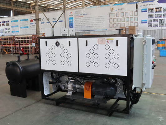
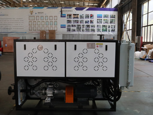
1. Main Body Installation: Ensure Stability and Uniform Loading
Leveling: Use a spirit level to check the base of the furnace to ensure that the vertical and horizontal deviations are ≤1‰. This prevents tilting that could cause uneven load on the furnace tubes and poor thermal oil flow.
Securing Method: Use anchor bolts (bolt specifications must match the equipment manual). Tighten evenly to prevent base deformation. For skid-mounted equipment, ensure the skid is firmly attached to the ground and free of wobbling.
Accessory Inspection: Before installation, calibrate the safety valve (set pressure meets design requirements, such as 1.05 times the operating pressure) and the pressure gauge (range 1.5-3 times the operating pressure, accuracy ≥1.6), and display a certified label. Thermometers should be installed on the thermal oil inlet and outlet pipes to ensure accurate monitoring.
2. Piping System Installation: Prevent Leakage, Gas Blockage, and Coking
Material and Welding: Thermal oil pipelines must be constructed of high-temperature resistant seamless steel pipe (such as 20# steel or 12Cr1MoV). Galvanized pipes are prohibited (the zinc layer easily breaks off at high temperatures, leading to coking). Welding should be performed using argon arc welding for the base and arc welding for the cover. Weld joints must undergo 100% radiographic testing (RT) with a pass level of ≥ II to prevent leaks.
Pipeline Layout:
Pipeline Slope: The thermal oil return pipeline must have a slope of ≥ 3‰, sloping toward the oil tank or drain outlet to prevent localized oil accumulation and coking. The slope of the oil outlet pipeline can be reduced to ≥ 1‰ to ensure smooth oil flow.
Exhaust and Drainage: Install an exhaust valve at the highest point of the pipeline (such as the top of the furnace or at a bend) to prevent gas accumulation in the system, which can cause "gas blockage" (localized overheating). Install a drain valve at the lowest point to facilitate regular cleaning of impurities and coking. Avoid sharp bends and diameter changes: Use curved bends (radius of curvature ≥ 3 times the pipe diameter) at pipe bends; avoid right-angle bends. Use concentric reducers when changing diameters to avoid eccentric changes that can disrupt oil flow and cause localized overheating.
Sealing test: After pipeline installation, perform a water pressure test (test pressure 1.5 times the operating pressure, maintain pressure for 30 minutes, no leakage) or a pneumatic pressure test (test pressure 1.15 times the operating pressure, maintain pressure for 24 hours, pressure drop ≤ 1%). After confirming no leaks, proceed with insulation.
Insulation: Pipelines and furnace bodies must be insulated (using high-temperature resistant insulation materials such as rock wool and aluminum silicate, with a thickness of ≥ 50mm). Cover with a galvanized iron protective layer to prevent heat loss and burns. The insulation layer must be tightly sealed to prevent rainwater from seeping in and causing insulation failure. 3. Electrical System Installation: Safety and Precision Control
Wiring Specifications: The electrical cabinet must be located away from heat and water sources. Power and control cables must be laid separately (use flame-retardant cable for power cables). Terminals must be securely fastened to prevent loose connections that could lead to overheating. The grounding system must be reliable, with a ground resistance of ≤4Ω (including the grounding of the equipment itself and the electrical cabinet).
Explosion-Proof Requirements: For oil-fired/gas-fired thermal oil boilers, electrical components near the burner (such as fans and solenoid valves) must be explosion-proof (e.g., Ex dⅡBT4) to prevent sparks from causing gas explosions.
Control Logic Check: Before commissioning, verify the electrical schematics to ensure that temperature control, pressure protection, and high and low liquid level alarms are functioning properly (e.g., automatic shutdown of the thermal oil when overtemperature occurs and burner startup prohibited when the liquid level is low).
II. System Commissioning: Verify Safety in Stages
1. Cold Commissioning (No Heating)
Check Pipeline Tightness: Fill the system with thermal oil (open the exhaust valve to expel all air during filling) until the oil level reaches 1/2-2/3 of the tank. Let it sit for 24 hours and inspect the pipes and welds for leaks.
Test the Circulation System: Start the circulation pump and check the operating current and noise level (current ≤ rated value, noise ≤ 85dB). Ensure that the thermal oil circulates smoothly within the system (touch the pipes to confirm there are no cold spots to avoid air blockage).
Verify Control Functions: Simulate faults such as overtemperature, overpressure, and low liquid level to verify that the alarms and emergency shutdown functions are functioning properly.
2. Hot Oil Commissioning (Gradual Temperature Increase)
Heating Rate Control: The initial temperature increase should be slow to avoid localized overheating and coking of the thermal oil. Specific requirements:
Room temperature to 100°C: Heating rate ≤ 20°C/h (to remove moisture from the thermal oil);
100°C to 200°C: Heating rate ≤ 10°C/h (to remove light components);
200°C to operating temperature: Heating rate ≤ 5°C/h (to stabilize the system).
Process Monitoring: During the heating process, closely monitor the pressure gauge (for no fluctuations or sudden increases) and the thermometer (for uniform temperatures at all points). If any piping vibration or temperature abnormalities (e.g., localized overheating of more than 10°C) are detected, immediately shut down the furnace for inspection to eliminate any air blockage or obstruction.
Nitrogen Gas Protection (Optional): If the thermal oil is used at a temperature ≥ 300°C, it is recommended to introduce nitrogen (slightly positive pressure, 0.02-0.05 MPa) into the oil tank to prevent oxidation from contact with air and extend its service life.
If you want to know more about our product, please contact us!
Post time: Sep-04-2025


